Project Description
Introduction
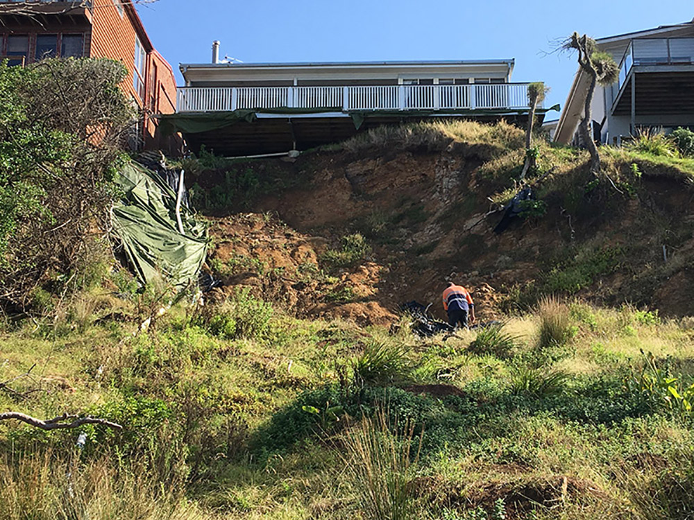
No 65 Sunset Strip is located on the south side of Inyadda Point in the township of Manyana, about 20 km north of Ulladulla. The site is a south facing allotment situated on the steep coastal escarpment slopes between Sunset Strip and the beach along the ocean shoreline. Remedial works were undertaken on the site to reinstate a failed slope along the site southern boundary.
2. Design criteria
The design criteria for the of the remedial design of the failed slope was detailed in TerraInsight’s Report (Ref TERRA170098 Rep 1 Rev 0 dated 25 March 2017) and provided as part of the development application.
3. Installation of piers and construction of strip footing
This report required that the piers for the strip footings should penetrate at least 1m into extremely to highly weathered rock which meets the following:
• Ultimate end bearing capacity of 1.8Mpa;
• Effective Friction angle between 28 and 30 degrees (30 degrees was adopted for slope stability analysis);
• Cohesion between 5 and 10 degrees (5 degrees was adopted for slope stability analysis).
At the time of inspection, piers were in the process of being augered using an 3.5 tonne excavator equipped with a 0.45m diameter auger. Piers had been augered to a depth of 2m (1m below target depth). Inspection of these pier excavations indicates they were founded in extremely to highly weathered, extremely to low strength, siltstone rock interbedded with moderately weathered, low to medium strength, sandstone. It is noted that the rock in the cutting observed at the time of the inspection had been exposed to the elements and had consquently softened.
The geotechnical Strength index for the rock as observed was assessed as between 10 and 25. This is consistent with a rock having an effective friction of between 15 to 30 and cohesion of between 10 and 30. Reanalysis of the slope was undertaken using a reduced friction angle of 25 degrees and an increased cohesion of 15 degrees with the piers modelled at 2m depth. This re-analysis indicates an acceptable factor of safety above 1.5. Terra Insight was not present on the day of concrete pour for the piers. However, Terra is aware the piers were inspected by a structural engineer prior to the concrete pour. The final depth of the piles and weathered rock encountered at the base of the piles was deemed to meet the design requirements.
4. Installation of addition row of gabions on downgradient slope
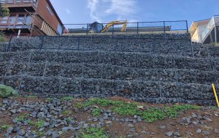
The remedial solution was designed to comprise three rows of gabion baskets, one located behind the strip footing. During installation of the gabion baskets, TerraInsight was informed by the site owners that the remedial works contractor had to install an additional row of gabion baskets. A site visit was undertaken to make observations of the constructed gabion baskets. It was observed that the additional row was required to merge with the existing ground surface profile to the west. The ground elevation in this area was about 1 m higher than indicated on the initial survey. Terra reviewed the stability analysis of the increased wall height, considering the additional 1 m gabions and the additional 1 m depth of piers below the strip footing. The global factor of safety for the slope was found to increase due to the additional weight the wall placed on the toe of the slope. There was no impact on the stability of the slope downstream of the wall, due to the additional depth of the piers. It was also noted that a berm had been left in place to the south of the strip footing, to protect the wall from erosion and to reinstate the slightly terraced area which was created here when the slope initially failed.
5. Installation of addition gabions on crest of slope
On completion of the wall. Terra was informed that an extra 1 m strip of gabion baskets had been added along the crest of the slope. In addition, gabion baskets had been installed along the western side boundary to retain the western edge of the granular filled slope. A visit to site was made to inspect the wall. The gabion basket had been installed to match the existing slope on the western boundary of the site. The gabion wall essentially replaced the top 1m of granular slope which was to be sloped at 45 degrees. As the rock is now contained in a gabion basket, stability analysis did not identify any reduction in the stability along the crest of the slope because of this addition. This addition also did not reduce the global stability of the slope below the required FOS=1.5. The additional gabions along the western side of the wall, will also assist with stability of the natural slope to the west of the site. Images showing the additional gabion basket at the crest and along the western site boundary are provided below.
6. Completion of wall
On completion of the remedial works, the site owners have identified a small section of slope, on the western boundary, that remains unsupported (refer Images 4). The slope is located on council land. It borders the site to the west. When and if remedial works are undertaken on the property to the west, this slope will be removed and replaced with a retaining wall of similar or different construction which will blend in with this wall and remove this slope. In the short-term, the site owners have placed large cobbles on the slope to provide protection from erosion and to ensure temporary stability of the slope. If the remedial works to the west are not undertaken, it is recommended that small native shrubs are planted on this section of the slope to assist in stabilising the near surface soils. Vegetation should also be reinstated on the lower slope on council land to the south of the wall (refer Image 5). It is also noted that instead of construction of the steps through the retaining wall as designed (allowing access to the toe of the wall), timber steps have been constructed to the south of the wall and along the eastern site boundary. These stairs have been inspected by A structural engineer from Front End Engineering.
7. Drainage Provisions
The design required that the following stormwater provisions:
• The retaining wall be constructed with drainage behind the wall;
• Stormwater drainage from the existing dwelling is collected and stored on site.
• Any overflow from the on-site storage and from behind the retaining wall is to be discharged to an outlet to be located on lower slopes on council land to the south of the site as detailed on the drawings submitted with the DA. During construction, changes were made to the stormwater design as follows:
• Weep holes were constructed through the retaining wall at regular intervals, rather than provision of a stormwater pipe behind the wall. It is noted that the fill placed behind the wall is coarse gravel and rock, and is free draining..
• In stead of installing the drainage pipe within the slope, the drainage pipe was installed on the ground surface. This minimising the potential for damage to the pipe when the rock fill was placed and allows for long term maintenance of the pipework.
• The outlet was relocated to discharge on to a tallus and ballast filled slope which was partly constructed in front of the wall during construction and partly deposited on the slope as a result of the slide.
These changes were not identified to have a negative impact on the design of the retaining wall.
8. Summary
In summary, there have been several changes to the profile of the remedial retaining wall during construction. These changes mean that most of the remediated slope is now comprised of gabion baskets with a small section of wall between the toe and crest, comprised of batter granular fill (refer image 3). At the crest of the slope, a small terrace has been constructed. The edge of this terrace is aligned with the terrace on the adjacent site to the west (refer Image 6). When and if this slope on the adjacent property (no 67 Sun Set Strip) is remediated, this terraced area can be blended in with the adjacent terrace on which the rear extension on No 67 is currently supported. This terrace also provides support to the failed section of land yet to be remediated on No 67 to the west of the site.


